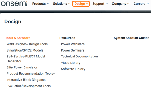
When it comes to system-level design, development tools are just as important to as finding the right solutions for your application. onsemi provides comprehensive tools and software that allow you to master your design process. Our tools are dedicated to help find the most suitable product and support you through the entire design cycle- from product selection to testing and analysis.
This blog provides an overview of some of our comprehensive tools so you can get started easily with your design.
Product Recommendation Tools+™
Finding the right product for your design can be overwhelming- from sorting through product datasheets to comparing specifications and features. The Product Recommendation Tools, or PRT+, are developed to help design engineers find the right product from onsemi’s product portfolio. The main advantage of PRT+ is the ranking algorithm that suggests the most suitable products. The ranking algorithm is based on the figure of merit of semiconductor components and user interaction with quick filters.
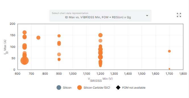
The PRT+ tool incorporates various advanced features to simplify part search. One of the features is interactive charts that provide a graphical representation of various portfolio parameters. The example below one shows the Rds(on) figure of merit (FoM) of the EliteSiC portfolio.
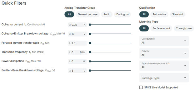
The tool also features a quick filter option, which gathers the most important parameters in one table to easily find your optimal solution.
The PRT+ tools also feature a Similar Products feature, which is accessible directly from many product pages.
WebDesigner+™
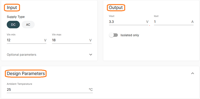
WebDesigner+™ Power Supply is an online tool that helps to design power supplies. Based on input-output requirements, the tool recommends PMICs and related electrical components. The required parameters are Min and Max input voltages, ambient temperature, output voltage and the output current of power source. The following operating ranges of input parameters are supported by the tool:
- Input voltage can be in the range from -40 to 1000 V.
- Output voltage from -65 to 100 V.
- Output current from 10 μA to 40 A.
- Ambient temperature from -40 to 175 °C
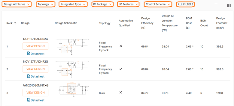
Based on these criteria, a list of potential products that meet the desired design requirements is displayed. Within this list, users can filter and choose the most suitable solution according to efficiency, topology, cost, footprint, and other parameters.
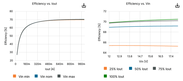
WD+ uses state-of-the-art mathematical models to calculate operating values like efficiency, losses, components temperature and more. The operating values are shown in interactive charts and tables, which help the users to quickly evaluate design suitability.
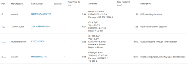
The tool creates a detailed design report complete with recommended bill of materials (BOM), schematic, design operation values and charts - all of which that can be shared with peers.
Elite Power Simulator + Self Service PLECS Model Generator
The Elite Power Simulator and Self-Service PLECS Model Generator from onsemi saves power electronic engineers time by providing state-of-the-art accurate simulations and product selection capabilities tailored to their specific application. The tools provide meaningful insights at an early stage of the development cycle, reducing costly and time-consuming hardware fabrication and testing.
When the Elite Power Simulator is used together with the Self Service PLECS Model Generator, designers can enter design-specific parasitic information related to their design environment and produce PLECS models with highly accurate system-level simulations.
As well as supporting the entire EliteSiC solutions portfolio, the tools have recently been expanded to include the Field Stop 7 (FS7) IGBTs.
System Solution Guides
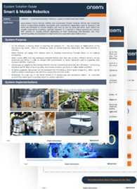
Our System Solution Guides are designed to help you navigate onsemi’s extensive product lines and find the most suitable products for your application.
These guides are an essential resource for your design project, including a combination of detailed technical specifications and practical development advice. They underscore onsemi’s expertise as a key component supplier and highlight our vast array of product offerings tailored for various applications.
Content of System Solution Guides:
- System Purpose
- Market Potential & Industry Trends
- Solutions and Sub-systems Overview
- Solution Block Diagrams
- Popular Topologies & Design Tips
- Key onsemi products benefits
- Recommended onsemi products
- Development Tools & Resources
DevWareX
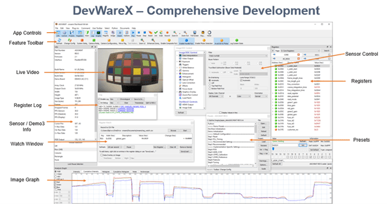
The development process of configuring, controlling, and verifying an image sensor can be a challenging task. onsemi provides a versatile and powerful tool known as DevWareX that can make this development process shorter, accurate, and more efficient.
This tool allows you to program your image sensor, display and evaluate images, along with running Python scripts to capture and save images. There are many built-in tools to help debug issues. There is also ApBase library, which is the associated software development kit (SDK) that allows the development of custom applications for image sensor control and image display.
SPICE Live Models
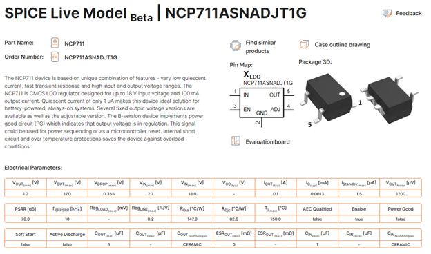
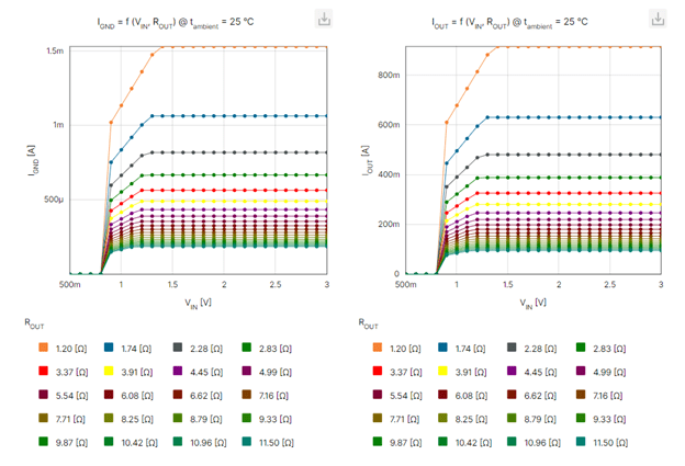
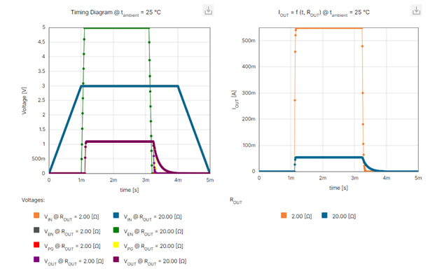
The new beta version of the SPICE Live Model tool currently supports selected products from our LDO , MOSFET, and BJT families. Simply click on the "SPICE" icon to access and manipulate various DC, Transient, and Monte Carlo simulations, and assess part performance in a web- based SPICE environment. The SPICE Live Model is designed for deeper exploration of onsemi components and application designs. Based on SPICE simulations, the tool provides enhanced information regarding product behavior and allows users to parametrize various simulation parameters and operating conditions. The tool also provides shortcuts to important product collateral, including datasheets and the evaluation board.
Within the tool, users can easily adjust simulation parameters and design components easily using application schematics.
The SPICE Live Model environment also allows users to output their evaluation results into interactive charts showing various operating parameters like: voltages, currents, efficiency, power dissipation and, in some cases, their statistical evaluation.
We encourage users to explore this new tool and share feedback to help us enhance functionality and overall experience.
Community Forums
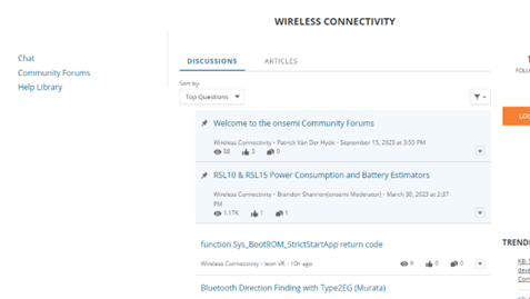
The onsemi Community Forums is designed to provide you with the best possible technical support for onsemi technology.
We designed the Community to be a robust platform where you can interact with other users of onsemi products, share your insights and experience and get answers to your questions from the onsemi support team and technology experts. You will also get access to a wide variety of up-to-date knowledge-based articles, interactive discussion forums and technical documentation on how to design using our products.
onsemi tools can significantly help users to find the right components and reduce the effort required to develop new products.
Learn more about onsemi’s comprehensive design tools and software today!
Additional Resources
